Container Houses: Design Trends And Construction Methods For 2026
Modular design, connectors, and on-site assembly for container housing
Modular strategies for container assemblages often rely on repeatable connector details that allow units to be stacked, splayed, or offset while preserving structural continuity and weatherproofing. Typical connector types include bolted splice plates between cut framing members, custom steel brackets that pick up roof loads, and adapter frames that align container corners to foundations. Designers frequently plan for tolerances in site conditions so connectors can be engaged without inducing unintended stresses; adjustable shims and grout pads are common tools to manage small misalignments.
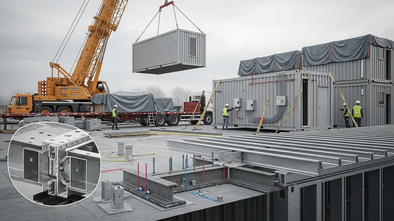
Transport and handling constraints shape module dimensions and connector design. Standard container widths and heights inform interior planning and orientation of service cores, while openings for cranes, trucks, and staging areas guide erection sequencing. Prefabricated service modules that house plumbing and electrical risers may be installed as discrete units before enclosure, which can simplify final connections. Sequencing plans that describe temporary bracing, lifting points, and weather protection typically reduce on-site risk and help maintain schedule predictability.
Weather and sealing details at connectors are vital for durability. Flashing, overlapping membranes, and rain screen principles are often applied where units join to prevent water intrusion. Designers may use continuous roof and wall membranes that bridge connectors or employ gasketed flange systems to allow movement while preserving watertightness. Thermal bridging at connector lines can be reduced by introducing insulated plates or thermal break spacers, balancing structural continuity with energy performance goals.
Service integration and future adaptability are factors in connector planning. Creating accessible cavities at connection zones makes it easier to route and maintain utilities between modules. Where future reconfiguration is a consideration, designers may prefer mechanical, bolted connectors that can be disassembled rather than permanent welded splices. Documentation of as-built connector locations and reinforcement details supports maintenance and helps future owners understand the assembly’s limitations and capacities.