Pipeline Girth Weld Testing: Methods And Technologies Explained
Common Inspection Techniques in Pipeline Girth Weld Testing
Pipeline girth weld testing commonly involves a set of techniques, each suited to particular defect types and operational scenarios. Ultrasonic testing is often favored for its capacity to measure wall thickness and identify planar imperfections. By using transducers, ultrasonic methods send sound waves through the weld and analyze reflected signals to estimate discontinuity characteristics. This electronic readout can support efficient evaluation, especially in automated field operations.
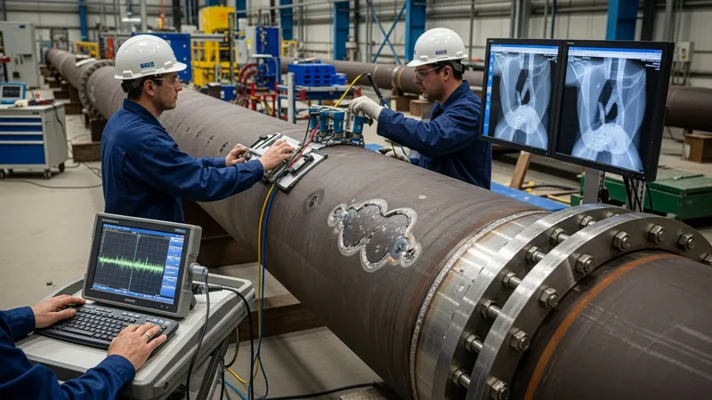
Radiographic testing may be selected when volumetric flaws, such as gas pockets or slag, are of primary concern. The resulting images provide a permanent visual record, which may assist in post-inspection assessments or independent reviews. When using radiography, both X-ray and gamma ray sources could be selected depending on weld thickness, accessibility, and local safety protocols.
Another widely adopted method is magnetic particle inspection. Applied mainly to accessible external surfaces, MPI enables rapid surveys for surface-breaking cracks that might extend longitudinally or transversely along the weld. The inspection requires appropriate magnetic fields and typically uses fluorescent or visible particles to highlight any discontinuities present in the weld area.
Each of these inspection methods can be used independently or in combination, depending on quality requirements and material type. The adaptability of these methods allows operators to tailor their inspection approach according to project complexity, operational constraints, and established industry codes. Future pages will investigate technology selection and data interpretation practices.