
Food Industry Metal Detectors: Principles Of Operation And Key Components

Detection coils, sensors and material response characteristics within food industry metal detectors
Coil geometry and sensor arrangement play a central role in detection capability. Common coil types include single-axis and multi-axis arrangements; balanced, differential receiver coils are used to suppress the nominal field and reveal disturbances caused by metal. Aperture shape—rectangular for conveyors, circular for pipes—affects field uniformity and sensitivity distribution across the opening. Sensor electronics incorporate analogue front-ends and digital sampling to detect small changes; some systems allow frequency switching or simultaneous multi-frequency sampling to optimize response to different metals.
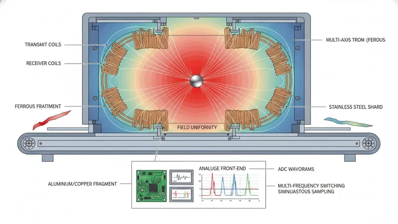
Sensitivity metrics are frequently expressed using standardised test pieces, such as a metal sphere of defined diameter and composition placed at the aperture centre. This provides a repeatable reference but may not fully represent how elongated or irregular objects behave. Ferrous materials often produce stronger responses per unit mass than non-ferrous metals; aluminium and copper generally require larger volumes to produce equivalent signals. Stainless-steel grades vary: martensitic or ferritic grades may be more detectable than austenitic grades, which may require higher sensitivity or specific frequencies to register reliably.
Pipeline and conveyor sensor configurations differ in practical terms. Pipeline detectors are designed to transfer minimal mechanical stress to the line and to maintain sanitary surfaces; coil placement and pipe-wall thickness are specified to preserve field coupling. Conveyor detectors must cope with motion, product misalignment and belt metallic components; as such, coil assemblies are often mounted in hygienic housings with easily removable detection heads for cleaning. For both types, manufacturers or technical references may provide guidance on expected sensitivity ranges for common metals and product types, though on-line verification remains important.
Calibration practice and test-piece use are essential for operational assurance. Test pieces of varying metal types and sizes are commonly run through the line at defined intervals to verify that the detector responds at the expected sensitivity setting. Calibration procedures may include adjusting gain, setting detection thresholds and logging results to a quality-management system. Records of verification tests often support internal quality audits and compliance with food safety standards; they may also aid troubleshooting when product or packaging changes affect baseline signals.